Tag Archives: box structural design

The deep analysis of the semi-automatic end lock structure

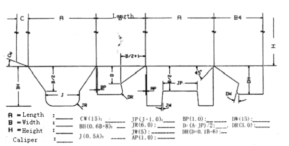
    Users with CAD or manual drawing out a semi-automatic end lock structure, like the below end lock structure, you should first have a very clear mind of relationships of the sizes of the bottom main parts details.

      The bottom sizes have close relationships of the main dimensions of the box, and the sizes of the length and width of box and the relationships influence the bottom structure.

    Length as L, width as W and thickness of the paper is CAL. (the structure described here is L/4 > = W / 3, if L / 4 < W / 3, this structure does not not recommend, on the one hand the paper utilization rate is not high, on the other hand is a load at the bottom is not good enough.)

    The first part, the relationship between the L,W dimensions and the main bottom sizes:

end lock1

Y1 = W / 2,
Y2 = Y1 – CAL / 2 ( As long as Y2 is close to Y1 or smaller than Y1, depending on the paper type)


end lock 2

X1 = (W – CAL) / 2
X2 = (L – X1 * 2)
The X3 = X2 + CAL
Y3 = W / 4 (roughly equal to the value, can be a little smaller than it, had better not exceed W / 4)
The rest is each corner fillet, will be no more description here.
    The second part,the various deformations:

The first:

      Bottom of the left is enhanced, very strong, the following is a deviation angle: T1 = 30 (c).

end lock 3


The second:

      For oblique incision on the left, the right for straight incision, T2 = 5 is an offset angle, the difference is not big. But the left side molding is more convenient.

end lock 4

The third:

       Left for bevel, right for right-angle, T3 = 30 is a deviation angle, if coupled with the first enhanced one on the left side of the end-lock structure, the bottom of the box will buckle more tightly. But the buckle will be a little trouble.

end lock 5


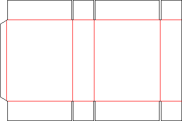
Fourth: position change

       In terms of a single box type structure, this change basically means nothing, but sometimes in order to meet the demands of layout, in order to improve the utilization rate of the paper, will be carried out in this end-lock structure. Then step and repeat.

end lock 7
       This paper utilization rate is increased obviously in this end lock structure.

end lock 8
        Finally, when the L value is too large, and the goods in the box is rather heavy (common fruit box), we can make the structure become polygonal to bear more load. This kind of end -lock structure is relatively complex, will be analyzed separately in a later article .
  end lock 9

How to check carton box structure with 3D module

For box structural designers, when design a carton box template for clientele it is quite challenging to check if the box structural design is cost-effective or otherwise with no physical reference. Within the following paragraphs we’ll talk about using Packmage CAD software program three dimensional lines mode to determine the rationality from the carton box.

Within the beginning, we’ve to uncover a die line template in Packmage CAD box template library, as an example, footwear box template.

box templates

box templates


The photo above
could possibly be the die type of footwear box template, there’s a interior lock structure around the lid from the shoe box. Right after we finished the structural style in the shoe box according to the necessary size, we’ll check out the 3 dimensional mode look into the structural style.
shoe box template

shoe box template

Look at the photo above, we’re still not apparent for several size particulars by way of this 3 dimensional box modeling picture, or doubt the if the dimensions of shoe box are reasonable or otherwise. For instance, the lid structure from the shoe box can not be observed completely.
box templates

box templates


In Packmage CAD
software program, we are able to transform to lines mode by press short-cut crucial L inside the 3 dimensional interface.
carton box template

carton box template

box templates

box templates

All through this mode, we’re in a position to appear in to the complete structure from the shoe box clearly, and also the whole process is easy adequate. Nonetheless, a single aspect we’ve to give consideration, due to the fact the 3 dimensional module shows the fabric from the shoe box, which means it’ll display the caliper from the paper, so before we use line mode to identify the box structure in three dimensional module, we ought to alter the caliper value into in Parametric style interface.

Tubular box structural design

The theory of carton box design is a little complicated, In this article we will talk about the structural design formula and some commonly tubular box structural design.

Size E EX B4 V FX  
D=Caliper
<0.45mm B-D D B-D D D  
046-0.65mm B-D D B-D D D  
0.66-0.99mm B-D D B-D D D  
1.00-1.80 B-D D B-D D D  
Size ZX Z4 YH S N FS
D=Caliper
<0.45mm 3 3 D+0.5 D F/4

mm

D
046-0.65mm 3 3 D+0.5 D
0.66-0.99mm 3 3 D+0.5 D
1.00-1.80 3 3 D+0.5 D

Note: When FX and Y equal 0, E=B

structural design       A


17mm<=A<=30mm 30mm<A<=100mm 100mm<A<=150mm A>150mm
  F=10mm F=13mm F=15mm F=18mm
      —–C—–      —-YZ——      —–G—–
Glued Piece


Rule


A>60       Y=7.5,Z=5.0


Dust Flap


Formula1


Formula 2       


The following can be ignored

——————————

Note:The following parameters can be changed according to requirements

G=1/2 or G=B4


Formula 3

tube box design

Structure of the end of the tubular folding carton box

1、Tuck end

tuck end box

2、Lock-End

lock end box

3、Self Lock End

self lock end box

self lock end box structure

4、Glue End

glue box

glue box structure